A Needle Roller Bearing uses long, slender cylindrical rollers to support radial loads in a compact space. The rollers have a small diameter compared with their length, allowing the bearing to fit where a conventional ball or roller bearing may be too large. Inside, the rollers move between raceways, which may be formed by separate rings or, in some designs, by a hardened shaft and housing. A cage can keep the rollers spaced evenly. The exact arrangement depends on the bearing type.
How does it work? As the shaft turns, the rollers roll along the raceways and spread the load across multiple contact points. This rolling contact can reduce friction compared with direct sliding, but it does not eliminate wear or heat. That matters. Lubrication, alignment, clearances, speed, and cleanliness all affect performance. A bearing’s load capacity also depends on its construction and operating conditions, so a catalogue rating should not be treated as a universal guarantee. Not always.
Needle roller bearings appear in gearboxes, pumps, agricultural machinery, and other assemblies where radial support and limited space are key concerns. Some versions are not designed to carry significant axial loads on their own; separate thrust components may be needed. It is easy to focus on the bearing’s small footprint and overlook installation details. A damaged raceway or poor fit can undermine an otherwise suitable choice. This guide explains the main parts, operating principle, common designs, and practical selection factors, while emphasizing the manufacturer’s specifications for each application.
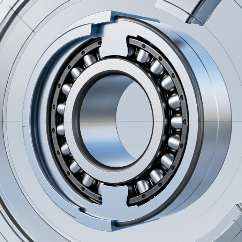
A needle roller bearing uses long, slender cylindrical rollers to support radial loads within a compact space. Compared with a ball bearing of similar bore, its smaller rolling elements can provide a thinner radial section. Inside the bearing, rollers run between raceways, spreading load across narrow contact lines as the shaft turns. This geometry suits gearboxes, pumps, and other assemblies where housing space is limited. Small, but useful.
Needle bearings may include an inner ring, or use a hardened shaft as the raceway. That choice affects installation and shaft requirements. The raceway must be hard, smooth, and accurately aligned; otherwise, concentrated contact stresses can accelerate wear. The trade-off is easy to miss: compact dimensions do not remove the need for careful lubrication or alignment. ISO 281:2007 calculates basic rating life for roller bearings as L10 = (C/P)^(10/3) million revolutions, where C is the basic dynamic load rating and P is the equivalent dynamic load. This is a statistical rating, not a guarantee for every application.
Tips: Check shaft hardness and surface finish before selecting a shaft-guided design. Keep lubricant clean, and confirm operating load and speed against the bearing’s technical data. If the housing is thin, verify its stiffness too; a flexible seat can disturb roller contact.
A needle roller bearing uses long, slender rollers to carry radial loads in a compact space. The rollers are its main load-carrying elements. Their small diameter allows the bearing to fit where a ball bearing may be too wide. Each roller contacts the raceway along a narrow line, distributing load along a longer path than a point contact. The geometry matters.
The outer ring, or housing raceway, guides the rollers and supports them against the surrounding structure. Some designs also use an inner ring; others run directly on a hardened, finished shaft. A cage keeps the rollers separated and helps them move evenly. Full-complement designs omit the cage to fit more rollers. More rollers can increase load capacity, but friction and heat may also rise. Small clearances matter. End rings or shoulders may retain the rollers, depending on the bearing type.
Lubricant forms a thin film between rolling surfaces and helps limit wear. In practice, shaft finish, alignment, and lubrication strongly affect service life. A bearing can look sound yet run hot if the shaft is rough or misaligned. Worth checking. I would not judge the bearing separately from the shaft and housing it runs in.
What Is a Needle Roller Bearing and How Does It Work?
How a Needle Roller Bearing Transfers Loads
A needle roller bearing transfers force through long, thin rollers positioned between a shaft and a hardened raceway. When a radial load presses on the shaft, the shaft pushes against the rollers. The rollers then press against the outer race or housing, carrying the force into the surrounding structure. That is the load path. Because the rollers are slender, several can fit around the shaft, spreading the load across multiple contact zones. Contact stays narrow. This line contact can support substantial radial loads in a compact space, though it does not eliminate stress at the raceway.
A cage, when present, keeps rollers spaced and helps prevent them from rubbing together. Some designs omit the cage and use more rollers, but the available speed and lubrication conditions matter. Grease or oil separates moving surfaces and helps limit heat and wear. The raceways must also be hard and accurately aligned; otherwise, rollers may load unevenly. In real assemblies, this is not always textbook-neat. A small shaft deflection or a particle in the lubricant can change how force is shared. Standard radial needle bearings have limited capacity for axial loads, so the bearing arrangement must account for forces acting along the shaft.
A needle roller bearing transfers radial load from the shaft through the inner race, needle rollers, and outer race to the housing. The chart shows the overall load path normalized to 100%—it does not represent the load on each individual roller.
In operation, multiple rollers share the load in the loaded zone. The actual load on each roller varies with bearing geometry, clearance, alignment, and operating conditions.
Needle roller bearings use long, thin cylindrical rollers to carry radial loads within a compact space. Their small roller diameter allows a relatively low-profile assembly, useful in gearboxes, pumps, and other mechanisms where housing space is limited. Under load, the rollers run between inner and outer raceways, spreading force along narrow contact lines. This can provide high radial load capacity for the bearing’s size, but it does not automatically make the bearing suitable for axial loads. Space is tight.
Design differences affect mounting, lubrication, and load handling. Drawn-cup needle bearings have a thin, pressed outer shell and often suit compact housings; some versions run directly on a hardened shaft instead of using an inner ring. Solid-ring designs are more rigid and can support heavier service, though they generally need more space. Caged types keep the rollers separated, reducing friction at higher speeds. Full-complement types fit more rollers and can carry greater loads, but their rollers rub against one another, which can limit speed. Thrust needle bearings handle axial loads and are installed with suitable washers or raceways. It is easy to overvalue load capacity on paper: shaft hardness, alignment, lubrication, and operating speed also shape real performance. The right choice depends on the assembly, not just the bearing dimensions.
Needle roller bearings use long, thin rollers to carry radial loads in a compact space. Their small cross-section suits automotive transmissions, pumps, agricultural machinery, and machine-tool assemblies where room is tight. A designer can fit them around a shaft without adding much radial bulk. Useful, but not magic.
The main advantage is high radial load capacity relative to bearing size. ISO 281:2007 defines the basic rating life, L10, at 90% reliability under specified operating conditions. It is a calculated benchmark, not a promise that every bearing will reach that life. These bearings are less suited to significant axial loads, and misalignment can concentrate stress on roller edges. Clean lubricant matters; a small grit particle can mark a raceway. In many designs, the shaft itself must provide a hardened, accurately finished raceway, adding manufacturing work. This trade-off is easy to overlook. Check load direction, speed, lubrication, and alignment together before selecting one.
| Topic | How It Works or Typical Use | Advantages | Limitations and Design Considerations |
|---|---|---|---|
| Basic construction | A needle roller bearing uses long, slender cylindrical rollers between inner and outer raceways, or between a shaft and a prepared housing raceway. | Its small roller diameter allows a compact radial cross-section. | The shaft or housing may need a suitably hard, smooth, accurately finished raceway when a separate bearing ring is not used. |
| Load and motion | The rollers distribute radial load along their length while rolling between the raceways as the shaft rotates. | Can provide substantial radial load capacity for its size compared with many other rolling-bearing arrangements. | A standard radial needle roller bearing is not designed to carry significant axial load; axial support generally requires a separate thrust bearing or suitable combined arrangement. |
| Drawn-cup type | A thin, formed outer shell typically holds a needle roller-and-cage assembly; some designs are supplied with a closed end. | Offers a compact, lightweight arrangement and can be economical in suitable high-volume designs. | Housing fit, installation method, and the supporting housing structure matter; thin shells are not a substitute for a heavy-duty, thick-walled housing. |
| Caged and full-complement designs | A cage spaces and guides the rollers. A full-complement design fits more rollers into the available space and generally has no cage. | Caged designs can suit higher-speed operation; full-complement designs can offer greater radial load capacity in a given envelope. | Full-complement designs generally have more roller-to-roller contact and are often less suitable for high speeds than comparable caged designs. Actual limits depend on the bearing design and operating conditions. |
| Gearboxes and transmissions | Used to support shafts and rotating components where radial loads are present and installation space is limited. | A slim bearing cross-section can help keep assemblies compact. | Correct alignment, lubrication, clearance, and load distribution are important to avoid premature wear or damage. |
| Automotive and machinery linkages | May be used in pivots, rocker mechanisms, pumps, and other rotating or oscillating joints, subject to the specific design. | Compact radial support can be useful where a conventional bearing would require more space. | Oscillating motion, shock loads, contamination, and limited lubricant supply require careful application review. |
| Lubrication and environment | Lubricant separates contact surfaces and helps reduce friction, wear, and heat; grease or oil may be used depending on the application. | Appropriate lubrication and sealing can support reliable operation in a wide range of equipment. | Insufficient or unsuitable lubrication, dirt, moisture, and excessive heat can shorten bearing life. Sealing and maintenance requirements should be assessed for the operating environment. |
| Selection factors | Selection depends on radial load, speed, available space, shaft and housing design, operating temperature, lubrication, and expected service life. | A range of configurations can address different space and load requirements. | Load ratings and speed limits vary by bearing dimensions and construction; verify them against the relevant technical data and application conditions. |
It uses long, slender rollers to carry radial loads. Its compact shape fits assemblies with limited space.
The shaft presses against the rollers. They transfer force to the outer race or housing. A simple load path.
Their smaller rolling elements can create a thinner radial section for a similar bore. The fit can be useful in tight housings.
No. Some designs use a hardened shaft as the raceway. Check its hardness, surface finish, and alignment.
Rollers may carry load unevenly, which can speed wear. Even slight shaft deflection can matter.
A cage spaces the rollers and helps prevent them from rubbing together. Some designs omit it, but speed and lubrication conditions matter.
Standard radial designs have limited axial-load capacity. The assembly must account for forces along the shaft.
Confirm load, speed, lubrication, shaft finish, and housing stiffness. I could focus on the small size and miss those details.
For roller bearings, ISO 281:2007 uses L10 = (C/P)^(10/3) million revolutions. It is a statistical rating, not a promise.
A Needle Roller Bearing is a rolling-element bearing that uses long, slender cylindrical rollers to support loads in a compact space. Its main parts typically include the rollers, an inner and outer race, and a cage that keeps the rollers evenly spaced. In some designs, one or both races may be omitted when a suitable shaft or housing surface serves as a raceway.
As the bearing rotates, the rollers move between the raceways and spread the load across their contact surfaces. This arrangement gives the bearing high radial load capacity relative to its size, while different designs—such as drawn-cup, solid, and cage-guided types—suit different space and operating needs. Needle roller bearings are commonly used in transmissions, machinery, and compact mechanisms. Their advantages include a small cross-section and efficient load support; limitations include lower tolerance for misalignment and, in many designs, limited ability to handle axial loads. Proper selection depends on the load, available space, speed, and operating conditions.

VETOR GROUP